The first two inputs are A and B and the third input is an input carry as C-IN. The difference between a half-adder and a full-adder is that the full-adder has three inputs and two outputs, whereas half adder has only two inputs and two outputs. This adder is difficult to implement when compared to half-adder.
#HALF ADDER TRUTH TABLE AND CIRCUIT FULL#
So this limitation can be overcome by using the full adders. So, this is a main limitation of HAs once used like binary adder particularly in real-time situations which involve adding several bits. The main reason to call these binary adders like Half Adders is, that there is no range to include the carry bit using an earlier bit.
#HALF ADDER TRUTH TABLE AND CIRCUIT SERIES#
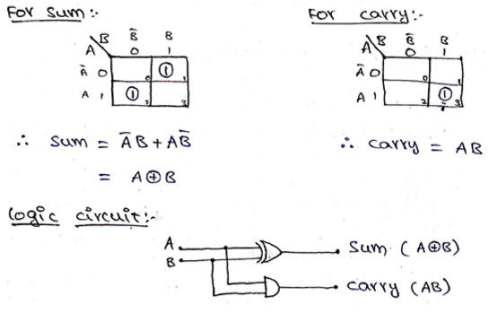
The implementation of half adder can be done through high-speed CMOS digital logic integrated circuits like 74HCxx series which includes the SN74HC08 (7408) & SN74HC86 (7486). The simplest expression uses the exclusive OR function:Īnd an equivalent expression in terms of the basic AND, OR, and NOT is:Īrchitecture Behavioral of the above circuit is With this theory, it was clear that the implementation is simple, but development is a time taking process. In a similar way, when you decide to make a four-digit adder, the operation is performed one more time. When you want to make a three binary digit adder, the half adder addition operation is performed twice. To perform the sum operation, XOR is applied to both the inputs, and AND gate is applied to both inputs to produce carry.Ī way to develop two-binary digit adders would be to make a truth table and reduce it. So, coming to the scenario of half adder, it adds two binary digits where the input bits are termed as augend and addend and the result will be two outputs one is the sum and the other is carry. Basic Half Adder and Full Adder Half Adder Below are the detailed half adder and full adder theory. It is already mentioned that the main and crucial purpose of adders is addition. This article gives detailed information about what is the purpose of a half adder and full adder in tabular forms and even in circuit diagrams too.

The full adder circuit has three inputs: A and C, which add three input numbers and generates a carry and sum. The half adder circuit has two inputs: A and B, which add two input digits and generates a carry and a sum. What is Half Adder and Full Adder Circuit? Adders are basically classified into two types: Half Adder and Full Adder. These can be built for many numerical representations like excess-3 or binary coded decimal. In many computers and other types of processors, adders are even used to calculate addresses and related activities and calculate table indices in the ALU and even utilized in other parts of the processors. An adder is a digital logic circuit in electronics that is extensively used for the addition of numbers.


 0 kommentar(er)
